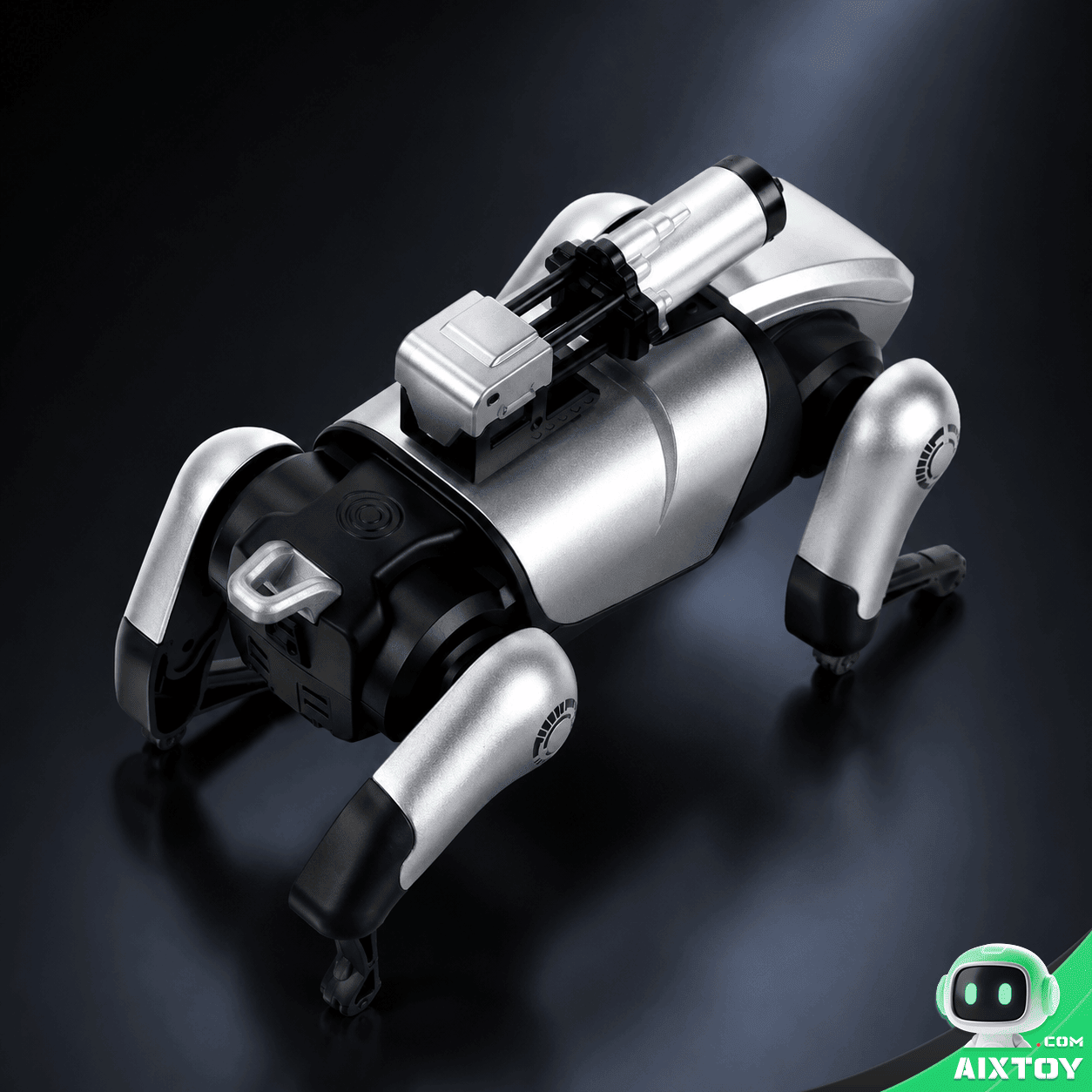




No products added!
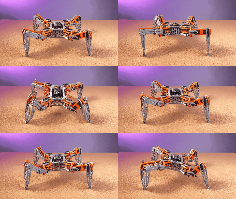
Welcome back to the NodeQuadMini assembly series. In Part 1, we covered hardware preparation and initial testing — verifying that every servo, sensor, and the ESP32 controller are functioning correctly before assembly begins. If you have not completed Part 1 yet, I strongly recommend starting there before proceeding. Today we tackle the mechanical heart of this quadruped robot: the legs and body assembly.
Important note: The leg assembly on NodeQuadMini reuses the same structural design as the NodeHexa hexapod robot. If you have already built hexapod legs before, you can skip directly to the Body Assembly section below. For first-time builders, read every step carefully — I have included a detailed troubleshooting guide based on real assembly issues reported by the builder community.
Body Assembly
The body frame assembly is surprisingly straightforward — a testament to clever structural design that minimizes part count while maximizing rigidity. Gather the following components before you begin:
- Robot mainboard
- Mainboard mounting bracket
- ESP32 development board (NodeMCU-32S)
- Body side brackets (left and right)
- Body rear bracket
- Body top plate
- Body bottom plate
- One M2×6mm screw
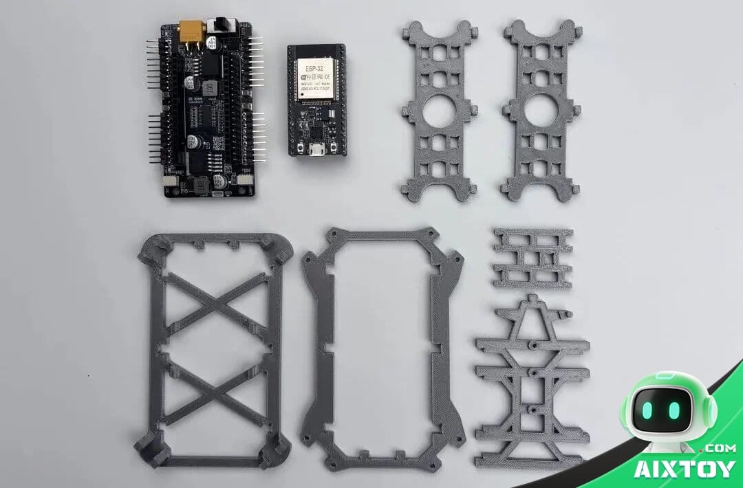
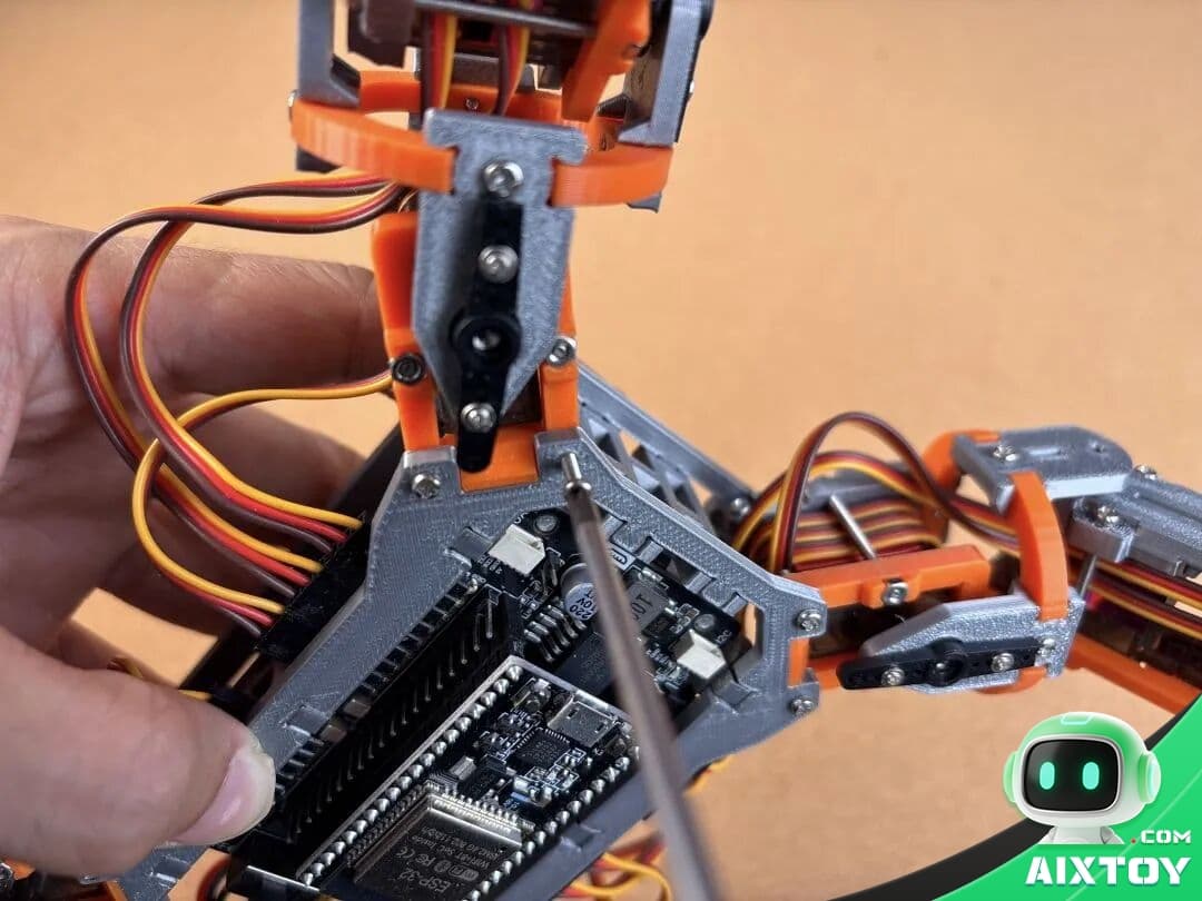
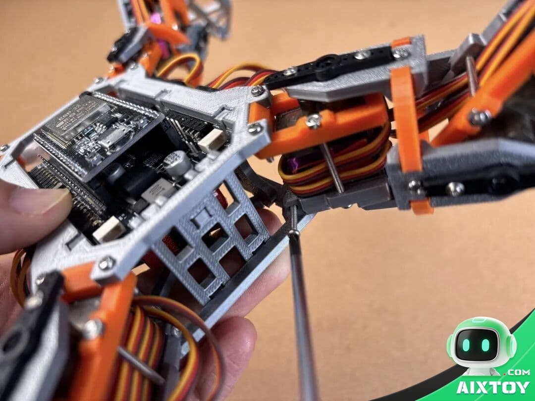
Step 1: Mount the robot mainboard onto its dedicated bracket. Secure it firmly with the mounting screws — the mainboard must not shift during robot operation, as any movement can cause intermittent electrical connections.
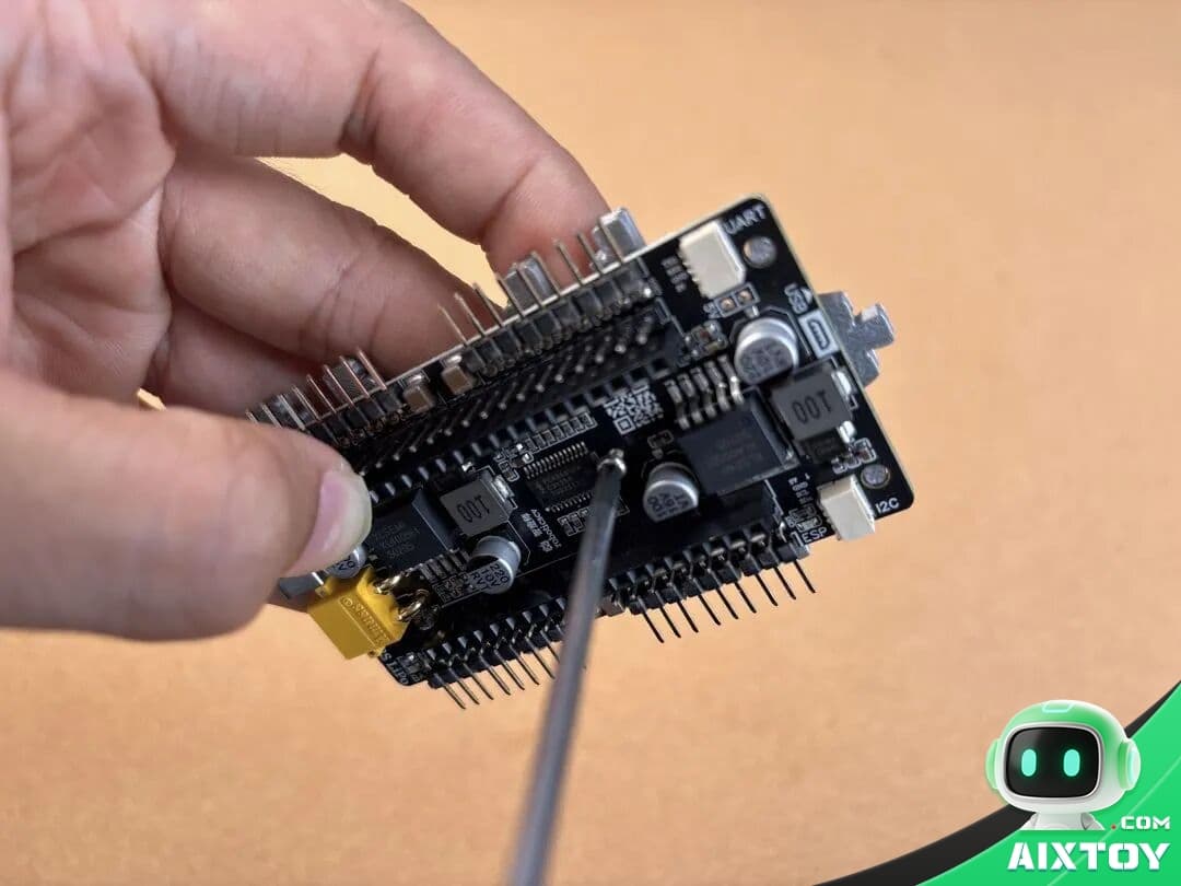
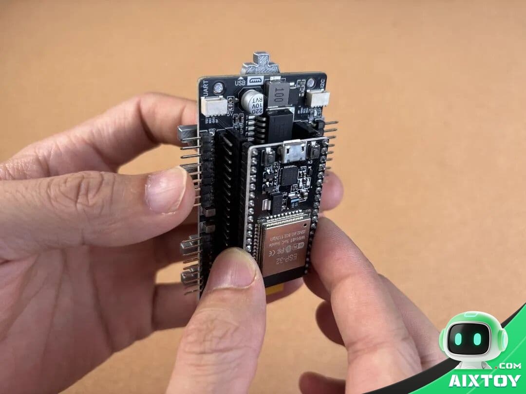
Step 2: Insert the ESP32 development board (NodeMCU-32S) into the mainboard connector.
Critical safety warning: Never insert the ESP32 board backwards into the mainboard connector! The mainboard has a USB silkscreen indicator showing the correct orientation. Reversing the connection will permanently damage the ESP32 — and this damage is not covered by warranty. Double-check the orientation before applying any pressure.
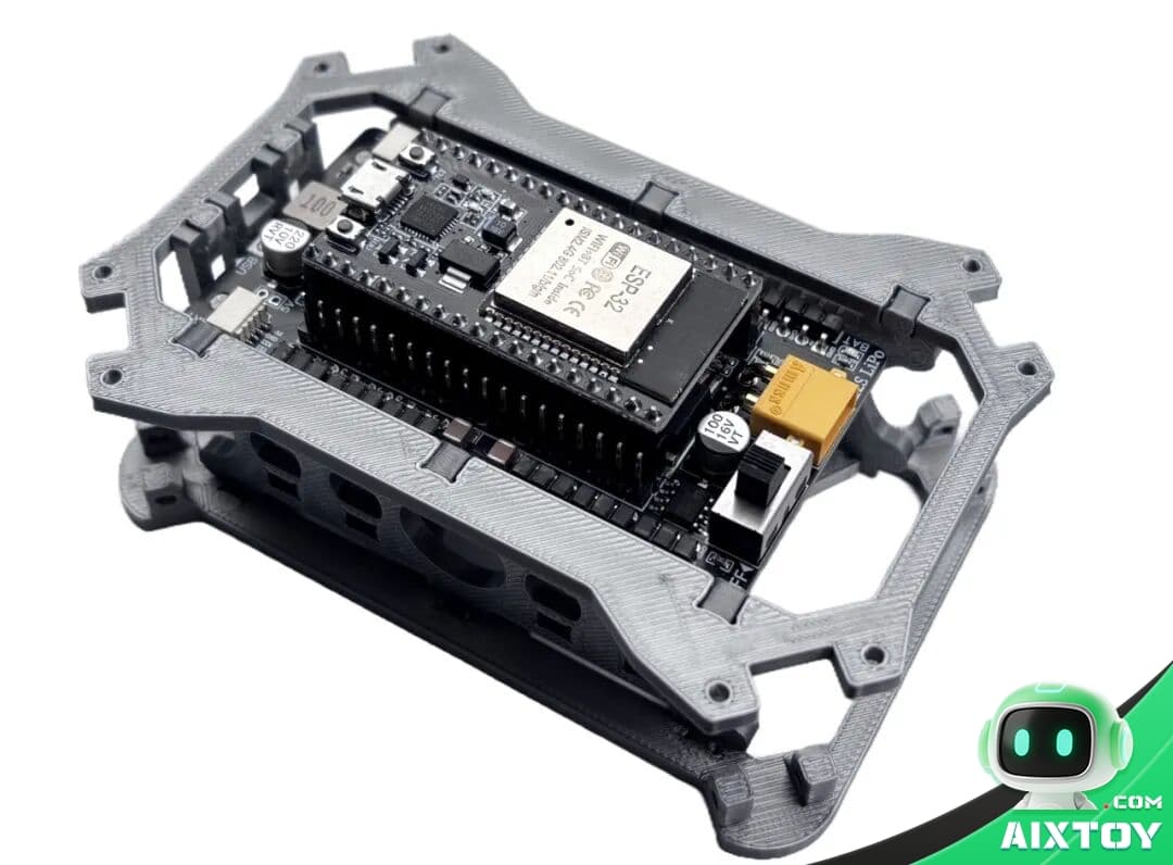
Step 3: Assemble the body frame. Connect the side brackets, rear bracket, top plate, and bottom plate as shown in the reference image below. The pieces are designed to interlock — no glue or adhesive is required. The friction fit is sufficient for structural integrity once all screws are in place.
At this stage, your body frame is complete. The entire body assembly should take no more than 15 minutes with all parts prepared. Take a moment to inspect the frame: all joints should be flush, no gaps should be visible at connection points, and the mainboard should sit securely without wobble.
Leg Assembly: Reference and Troubleshooting
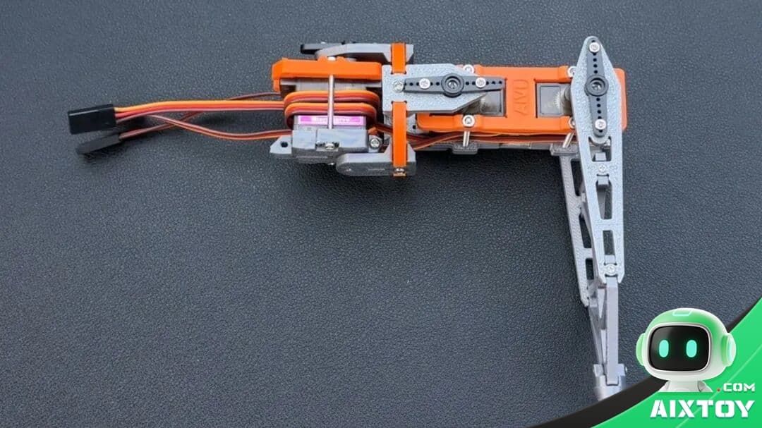
The leg assembly for NodeQuadMini is structurally identical to the NodeHexa hexapod. For the complete step-by-step leg build guide, refer to the NodeHexa Leg Assembly Tutorial. Below is a focused troubleshooting guide covering the four most common assembly mistakes — compiled from real customer feedback and community reports.
Issue 1: Servo Horn Initial Angle Misalignment
Servo motors have a fixed mechanical rotation range — typically 0° to 180°. During the calibration phase (covered in Part 3), we set each servo to 90° as the neutral “zero position” for its corresponding joint. If the servo horn is installed at a significantly incorrect angle during assembly — deviating too far from the intended neutral position — calibration will fail and the leg will not move correctly through its range of motion.
Prevention: All servos in the DIY kit ship pre-tested and pre-positioned at approximately 90°. Before attaching any servo horn, verify the servo is at its factory 90° position. Do not manually rotate the servo horn during or after assembly — this will defeat the pre-calibration. If you completed the hardware check in Part 1 and ran the “zero position” command, your servos should already be at the correct angle.
Issue 2: Reversed Connector Orientation
Servo-driven connectors are directional components. If a connector piece is installed backwards — rotated 180° from its intended orientation — the associated joint will move in the opposite direction. A joint that should rotate clockwise will rotate counter-clockwise instead. A single reversed connector can cause the robot to walk in circles, stumble, or fail to move entirely.
Prevention: Compare every connector orientation against the reference photos before tightening. Pay special attention to the direction of the servo output shaft relative to the connector. A reversed connector can take hours to diagnose later because the robot’s erratic movement does not obviously point to a specific joint. Getting this right during assembly saves enormous debugging time.
Issue 3: Overtightened Servo Bolts
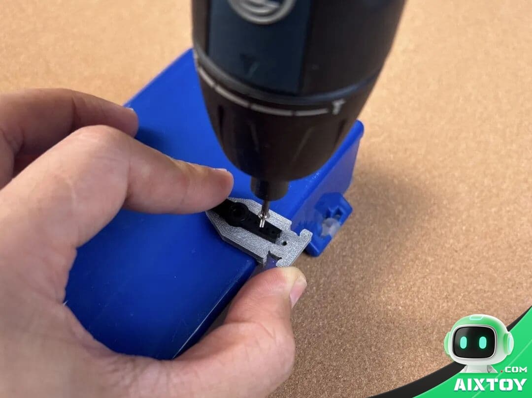
The M2×28mm bolts on both sides of each servo housing should be tightened to hold the assembly securely — but not excessively. Over-tightening compresses the servo casing, which increases rotational resistance inside the gear train. This additional friction can cause the servo to overheat, stall under load, or in severe cases, permanently damage the internal gears and motor.
Prevention: Tighten bolts until you feel resistance, then stop. The bolt should hold the assembly without play, but the servo housing should not be visibly deformed. A good test: after tightening, gently rotate the joint by hand (with the servo unpowered). It should move smoothly with light resistance from the gear train — not feel stiff or gritty.
Issue 4: Axle Pin Tolerance Problems
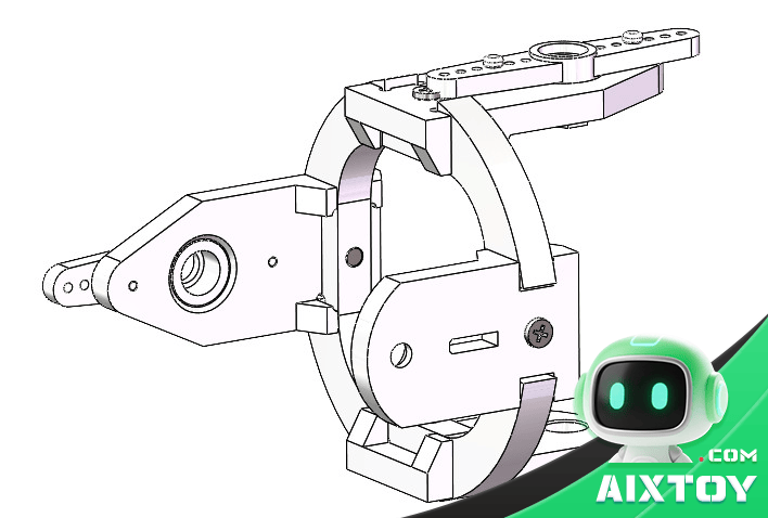
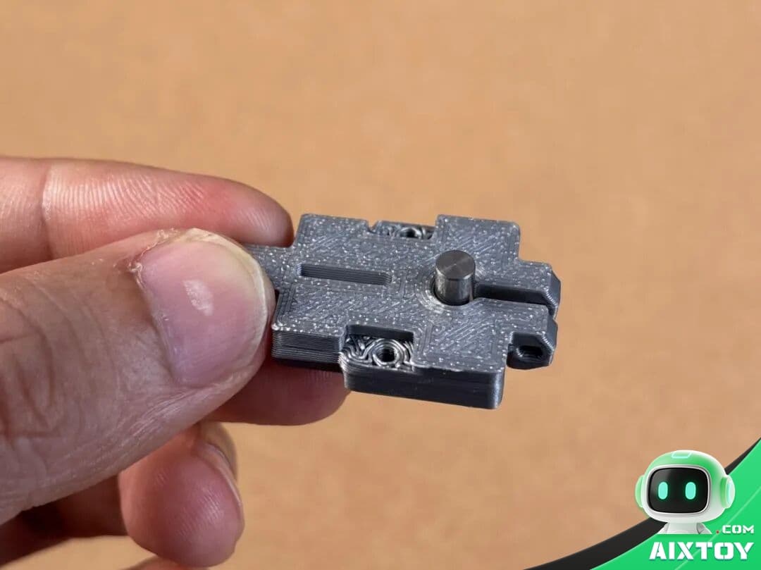
3D-printed parts have inherent manufacturing tolerance variation. Two holes with the same nominal diameter specification can end up with slightly different actual sizes due to printer calibration, filament properties, and layer adhesion characteristics. Axle pins from different production batches may also vary slightly in diameter. The result: some pins fit perfectly, some are too tight to insert, and some are loose enough to fall out during operation.
Fix for loose pins: Replace the pin with an M2 bolt and self-locking nut. This provides a secure, adjustable connection that will not vibrate loose during robot operation.
Fix for tight pins: Gently sand the pin surface with fine-grit sandpaper (400+ grit) or carefully ream the hole. Never force a pin that does not slide in smoothly — excessive force can crack the 3D-printed part.
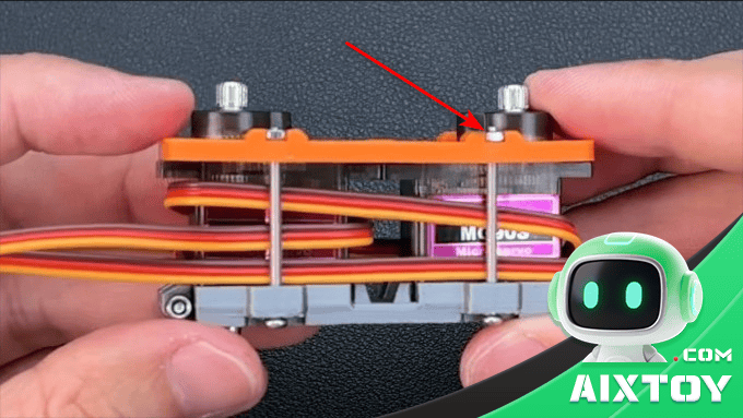
Attaching Legs to the Body Frame
This step requires patience and the right fasteners. Prepare the following hardware before you begin:
- 8× M2×10mm screws
- 4× M2×16mm screws
- 8× M2 self-locking nuts
- 4× M2 hex nuts
Attach each leg to the body frame at two connection points:
Top connection: Use M2×10mm screws with self-locking nuts, going through the body top plate. The locking nuts prevent loosening from vibration during walking gaits.
Bottom connection: Use M2×16mm screws with hex nuts, going through the body bottom plate.
Practical tip: During initial assembly and testing, you can temporarily skip the self-locking nuts. Assemble with regular nuts first, test the robot’s movement and gait, confirm everything works correctly — then install the locking nuts for permanent assembly. This approach saves significant disassembly time if you need to adjust a servo horn or connector orientation during calibration.
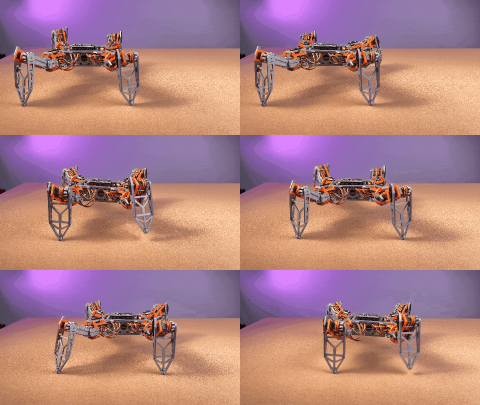
Once all four legs are attached at both connection points, take a step back and admire your work. You now have a fully assembled NodeQuadMini quadruped robot!
Next Steps: Bringing Your Robot to Life
In Part 3, we will connect all eight servo wires to the mainboard, flash the control firmware, and run through the calibration sequence that transforms a pile of assembled parts into a walking, responsive quadruped robot. This is where the build transitions from mechanical assembly to software and motion — and where the real satisfaction begins.
If you are following this series and have questions about your build, leave a comment or reach out through the contact form. The NodeQuadMini community is active and always happy to help troubleshoot.
Quick Reference: Tools You Will Need
- Phillips #00 screwdriver (for M2 screws)
- Tweezers (for handling small nuts and washers)
- Fine-grit sandpaper (400+ grit, for fitting adjustments)
- Needle-nose pliers (for holding nuts during tightening)
- Good lighting — these parts are small
Explore quadruped robots, DIY robot kits, and STEM learning tools at AIXTOY Shop.
Tags:AIXTOYDIY Robot AssemblyDIY Robot KitESP32NodeQuadMiniProgrammable RobotQuadruped RobotRobot KitSTEM Robot